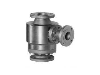
SUREFLO AUTOMATIC
RECIRCULATION VALVE
The SureFlo Automatic Recirculation Valve protects centrifugal pumps during low load operation and is available in sizes up to 16 inches and pressure class to ASME 2500#. The SureFlo AR Valve encompasses all of the hardware required in a conventional bypass system in a single housing.
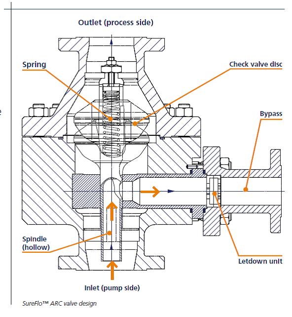
One Valve, Multiple Functions
All of Fetterolf's Pump Protection Valve designs (SurFlo,HighFlo and Custom) unite all of the elements in a conventional bypass system into one valve.
This includes the check valve in the main line which protects the pump from reverse flow and provides excellent pulsation dampening of the fluid, The bypass segment of the AR valve operates by sensing the main flow and automatically allowing the required minimum flow to enter the bypass. The AR valve also operates to reduce the pressure from the main line through the bypass to the storage tank for quite, safe and dependable operation.
The AR valve is therefore a check, bypass, minimum flow and pressure reducing valve all in one body.
Operation
Main Flow Only - Bypass closed (Figure 1)
When the process associated with the pump is in the normal operating condition, the main line is open.
The pressure created by the media (through the pump) is sufficient to compress the spring in the check valve disc part of the AR valve and lift itt from it's seat to the fully open position.
As the connected disc stem rises, the bypass exit in the in the stem funnel is closed. The bypass flow is therefore inversely proportional to the main pump flow. When the check valve is fully opened, the bypass is fully closed.
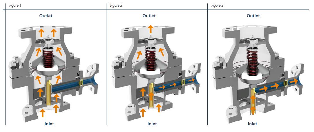
Combined Flow (Figure 2)
As the flow requested by the process is reduced the pressure on the disc spring is lowered and the disc moves towards its seat. The check valve part of the automatic recirculation valve moves first to a partially open position. In this position, there is partial flow to the main line outlet and a minimum flow to the bypass is maintained.
Bypass Only - No main Flow (Figure 3))
When no product is required by the process the valve disk returns to the seated position. There is insufficient flow to compress the spring and allow the disc to rise.
In this position, the curved part of the hollow stem is now flush with the entrance to the bypass funnel. A predefined minimum flow can now move from the pump through the bypass section of the AR valve and be recirculated to the front end of the pump. The pump is thereby protected from overheating or cavitation.
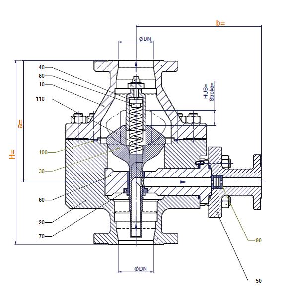
Drawing
Features
- 1" to 16 " as standard
- Pressure rating up to ASME 2500# (PN320)
- Carbon or stainless steel as standard
- Process seal: Metal to metal
- Connection Types: Butt weld end or flanged
Technical Data
| ARC Valve | Standard Features | Optional Features |
|---|---|---|
| Application | To protect pumps and ensure minimum flow conditions | |
| Size | 1” to 16” as standard | To 30” or larger as custom design |
| Body and bypass | Carbon or Stainless steel (316L) | Duplex, Hastelloy or Titanium |
| Valve Lining/Sleeves | n/a | Ceramic |
| Trim materials | Stainless steel (316L) | Duplex, Hastelloy, Ceramic, Inconel, Titanium or Tungsten Carbide for severe service applications |
| Spindle | Stainless steel 1.4404 (316L) | as above |
| Spring | Stainless steel | Inconel X750 (2.4669) |
| Temperature | Minus 20° to 300°C | Minus 100°C to 500°C |
| Process sealing | Metal to metal | n/a |
| Pressure rating | All up to ASME 2500 (PN320) | To ASME 4500# or higher on request |
| Connection types | Butt weld end or flanged (DIN or ANSI) | ISO, BS, JIS, NF on request |
| Heating jacket | n/a | Full or semi jacketing |
| Bypass trim design | Throttle plates | Multi stage, hollow, or cage trim in bypass |
| Control Characteristics | Linear | Equal % |
| Installation | Vertical | Horizontal |
| Flow direction | Flow to open, no reverse flow (integral check valve) | n/a |
| Other options | Maritime sea water service ARC design | Valves conforming to NACE MR-01-75 |
Benefits
- Protects the business investment in critical pump equipment
- Saves power costs by eliminating continuous recirculation to cool the pump
- Includes reverse flow protection
- Avoids additional investment in pressure reducing equipment
- Needs no electrical wiring, plant or instrument air
- Reduces downtime - and is easy to maintain
Dimensions
| Inlet/Outlet Size | Bypass Size | Pressure Class | a in mm | b in mm | H in mm |
|---|---|---|---|---|---|
| 1"/1"; DN25/25 | ½"; DN15 | ASME 150 | 188 | 145 | 271 |
| 2"/2"; DN 50/50 | 1½"; DN40 | ASME 300 | 283 | 236 | 425 |
| 3"/3"; DN75/75 | 3"; DN75 | ASME 300 | 277 | 295 | 420 |
| 4"/4"; DN100/100 | 1½"; DN40 | ASME 300 | 297 | 300 | 450 |
| 4"/4"; DN100/100 | 2"; DN50 | ASME 300 | 297 | 305 | 450 |
| 4"/4"; DN100/100 | 3"; DN75 | ASME 300 | 297 | 310 | 450 |
| 6"/6"; DN150/150 | 3"; DN75 | ASME 300 | 357 | 385 | 520 |
| 6"/6"; DN150/150 | 4"; DN100 | ASME 300 | 357 | 390 | 520 |
| 8"/8"; DN200/200 | 3"; DN75 | ASME 300 | 524 | 430 | 795 |